OpenPlant Modeler Help

Flanges Gallery

Used to place elbow components.

Accessed from the Piping ribbon.

The following gallery displays which can be left floating or docked to the drawing area.

Component <Component Class> in Placement Key In syntax (Mechaddin Place <Component Class> dsc=Piping)
Weldneck Flange WELD_NECK_FLANGE
Threaded Flange THREADED_FLANGE
Socketweld Flange SOCKET_WELDED_FLANGE
Slip On Flange SLIP_ON_FLANGE
Companion Flange COMPANION_FLANGE
Expander Flange EXPANDER_FLANGE
Filler Flange FILLER_FLANGE
Blind Flange BLIND_FLANGE
Spectacle Blind SPECTACLE_BLIND
Ferrule PIPE_FERRULE
Hub PIPE_HUB
Blind Hub PIPE_BLIND_HUB
Lap Joint Stub End LAP_JOINT_STUB_END
Orifice Flange Set ORIFICE_FLANGE
Reducing Slip On Flange REDUCING_SLIP_HY_ON_FLANGE
Reducing Threaded Flange REDUCING_THREADED_FLANGE
Reducing Weldneck Flange REDUCING_WELD_NECK_FLANGE
Reducing Filler Flange REDUCING_FILLER_FLANGE
Ring Spacer RING_SPACER
Victaulic Flange VICTAULIC_FLANGE

Placement

Placement of operator type components usually consists of the following common steps:

  • Set the size and spec in the Standard Preferences dialog.
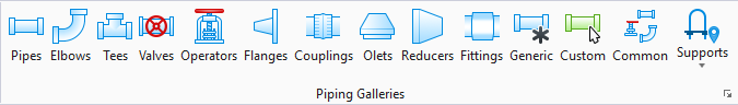
  • Select an option from the Flanges Gallery.
Note: If there is more than one record in the specification that meets the criteria, you are prompted to select a specific record from the Spec Record Selection dialog.
  • Define the Placement Point (Main Port, Run Port etc.) and settings in the Place Component dialog.
  • Use the mouse to pick placement, direction and rotation points as prompted.